| View previous topic :: View next topic |
| Author |
Message |
Rik
Site Admin

Joined: 07 Oct 2005
Last Visit: 25 Apr 2024
Posts: 1932
Location: California
|
 Posted: Wed May 12, 2010 10:28 am Post subject: Posted: Wed May 12, 2010 10:28 am Post subject: |
 |
|
That is pretty annoying. Some companies here have base starting price for shipping regardless of the order (usually $8-10). So, even if you just want a $0.25 part, you have to pay nearly $10 for it... Fortunately, I can find companies that don't do this (they are smart enough to realize a transistor can be mailed for less than a $1).
Good news though: I was able to locate the 152 in a local store (and the 85 also). So I'll send all three out to you, you can decide which to use and see if it works... It'll probably be Sat that I send them out.
Hopefully we can get the game working!
Rik |
|
| Back to top |
|
 |
J450N
Mattel Football
Joined: 27 Feb 2010
Last Visit: 12 Jan 2012
Posts: 12
Location: England, U.K.
|
| Posted: Fri Jun 11, 2010 3:44 am Post subject: |
|
|
Many many thanks Rik, I got the parcel this morning.
I've put the 152 in but I still don't have a working game. See below.

The start up tune is right but the display is not correct. The jump and directional buttons work.
Lower part of screen

As you can see the score is illegible and there are two bright columns (one with the character and one of the barrels) and the lower section is fully illuminated.
Any Ideas please ? Should I try replacing the 85 next or is it something more obvious ? |
|
| Back to top |
|
|
blanka
Atari Cosmos
Joined: 14 Dec 2010
Last Visit: 13 Oct 2022
Posts: 561
Location: Eindhoven, the Netherlands
|
| Posted: Wed Jan 11, 2012 12:52 pm Post subject: |
|
|
Still having the problem?
Check the solder points on the VFD tube. Mine had a few corroded ones resulting in some lines not showing at all. Maybe yours has a few that are connected wrongly. Look at the tube, from each section grid you see a pin going to the PCB. If one those grid mesh pins connect to one of the pins IN BETWEEN grid pins, you get a vertical line being lit. |
|
| Back to top |
|
|
J450N
Mattel Football
Joined: 27 Feb 2010
Last Visit: 12 Jan 2012
Posts: 12
Location: England, U.K.
|
| Posted: Thu Jan 12, 2012 1:05 am Post subject: |
|
|
| blanka wrote: | Still having the problem?
Check the solder points on the VFD tube. Mine had a few corroded ones resulting in some lines not showing at all. Maybe yours has a few that are connected wrongly. Look at the tube, from each section grid you see a pin going to the PCB. If one those grid mesh pins connect to one of the pins IN BETWEEN grid pins, you get a vertical line being lit. |
Thanks for the suggestion, but the top left vfd connections (about the first 5) are responsible for vertical lines in the game and it was the first place I looked. I deliberately run pins 3 and ground to short and it resulted in a brighter column but did not extinguish the rogue column when I removed the short. I haven't given up, the game is still on my workbench in two halves awaiting someone who can give me a solution. Thanks for your try / suggestion. |
|
| Back to top |
|
|
blanka
Atari Cosmos
Joined: 14 Dec 2010
Last Visit: 13 Oct 2022
Posts: 561
Location: Eindhoven, the Netherlands
|
| Posted: Thu Jan 12, 2012 3:34 am Post subject: |
|
|
The 5 top pins are not responsible for the vertical lines! I made a scheme for you:

Green pins are for the emitting wires, and they should have around -27V on them compared to the ground. NEVER CONNECT THESE TO ANY OF THE RED PINS, THE BLUE PINS OR ANY OTHER GROUND OR POWER LINE! If they reach a potential of more than 4-5V they fry and you can throw away your game.
The red pins are the grid pins, and they are scanned a few times per second.
The blue pins are the segment leads, and they connect 1 element in each segment vertically. As you can see, there are more blue leads than needed, 26 where the most dense segment only has 21 items. But as you can see, some of these blue pins are connected on the PCB, so it was probably not possible to reach all the segments with 1 pin on one side of the VFD.
So check all the blue pins and make sure they are not connected to any of the neighbouring red pins. If that happens, a vertical row lights up. |
|
| Back to top |
|
|
J450N
Mattel Football
Joined: 27 Feb 2010
Last Visit: 12 Jan 2012
Posts: 12
Location: England, U.K.
|
| Posted: Thu Jan 12, 2012 4:50 am Post subject: |
|
|
| blanka wrote: | The 5 top pins are not responsible for the vertical lines! I made a scheme for you:
Green pins are for the emitting wires, and they should have around -27V on them compared to the ground. NEVER CONNECT THESE TO ANY OF THE RED PINS, THE BLUE PINS OR ANY OTHER GROUND OR POWER LINE! If they reach a potential of more than 4-5V they fry and you can throw away your game.
The red pins are the grid pins, and they are scanned a few times per second.
The blue pins are the segment leads, and they connect 1 element in each segment vertically. As you can see, there are more blue leads than needed, 26 where the most dense segment only has 21 items. But as you can see, some of these blue pins are connected on the PCB, so it was probably not possible to reach all the segments with 1 pin on one side of the VFD.
So check all the blue pins and make sure they are not connected to any of the neighbouring red pins. If that happens, a vertical row lights up. |
Thanks for your efforts:
I'm getting -26.2v on the green outputs here is a photo of the problem what is the output from the red pins ( I suppose it varies depending if there is a call for them to be lit ?)
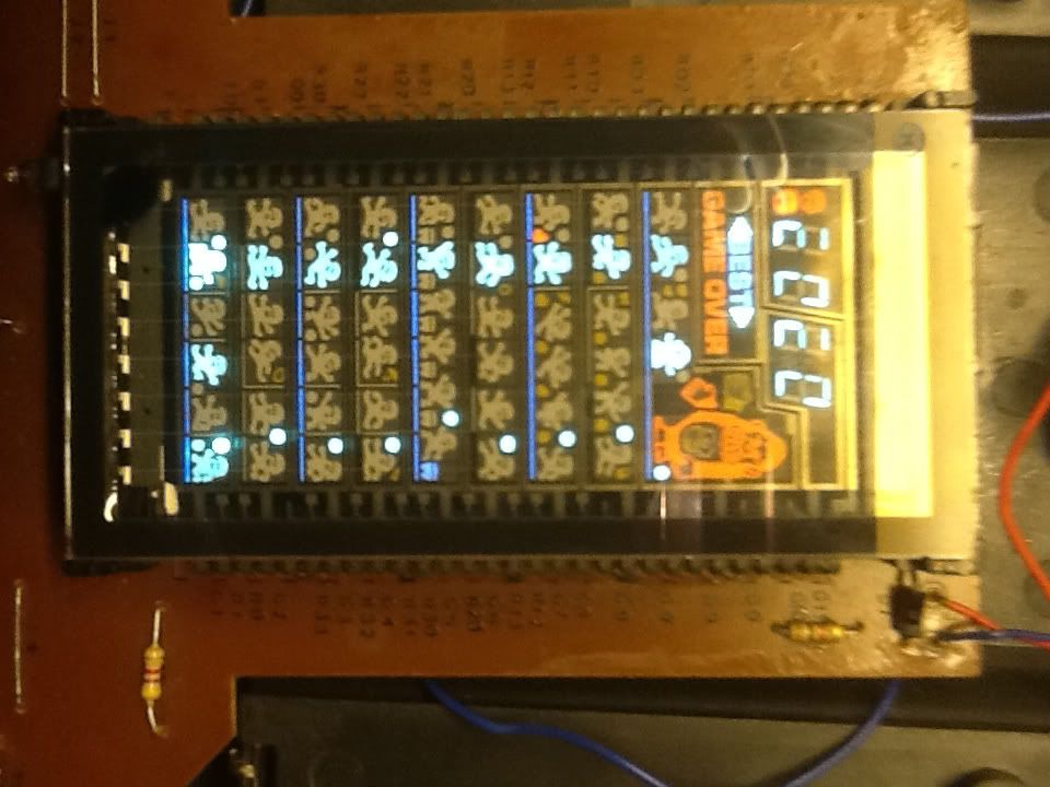
It actually looks relatively clean !
 |
|
| Back to top |
|
|
blanka
Atari Cosmos
Joined: 14 Dec 2010
Last Visit: 13 Oct 2022
Posts: 561
Location: Eindhoven, the Netherlands
|
| Posted: Thu Jan 12, 2012 5:34 am Post subject: |
|
|
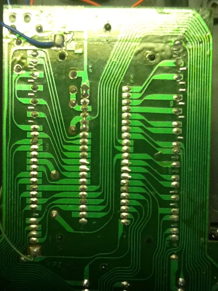
Turn the game off, and start measuring the resistance between adjacent red and blue pins. If one gives 0 ohm, then you need to use a knife to cut loose the lines.
-26.2V is fine
The voltage on the grid is rougly -30V (lower than the green pins), and gets connected to the ground when active (0v), usually during about 1/100 of a second in each display refresh.
Check the gaps between solder points like on this image:
 |
|
| Back to top |
|
|
J450N
Mattel Football
Joined: 27 Feb 2010
Last Visit: 12 Jan 2012
Posts: 12
Location: England, U.K.
|
| Posted: Thu Jan 12, 2012 6:26 am Post subject: |
|
|
| Ok I've measured each connection and looking top left top most pin and next one I get zero ohms nothing on others until I get to the last two above the speaker wire and I get some resistance but not zero .... All other connections appear open. Top right hand side the same I get zero for the first two pins on the vfd and some resistance on the last two but not zero with the game off. |
|
| Back to top |
|
|
|