| View previous topic :: View next topic |
| Author |
Message |
bobmoo79
Microvision
Joined: 07 Dec 2018
Last Visit: 14 Apr 2021
Posts: 25
Location: Southampton, UK
|
 Posted: Fri Dec 07, 2018 9:43 am Post subject: Astro wars / galaxy ii repair Posted: Fri Dec 07, 2018 9:43 am Post subject: Astro wars / galaxy ii repair |
 |
|
Hello to all, new member here!
I acquired a faulty astro wars game by grandstand.
It does nothing when powered from battery or power adapter.
When the power is switched on the voltage drops to around 1.5v and the power transistor (d882) gets very hot very fast. I swapped the transistor but get the same problem with the replacement.
I get 0v on the cpu power pin.
The machine seems to draw 1.5A across the power switch contact pads (bridging the pads with the multimeter).
I was going to sketch out the schematic but haven't got around to it yet so wondered if anybody here has one already done and whether anybody has more ideas about what I can try to fix this little fella. Can anybody help??
  
Here is the BOM I have managed to piece together so far.

Last edited by bobmoo79 on Wed Jan 09, 2019 1:28 am; edited 6 times in total |
|
| Back to top |
|
 |
blanka
Atari Cosmos
Joined: 14 Dec 2010
Last Visit: 13 Oct 2022
Posts: 561
Location: Eindhoven, the Netherlands
|
| Posted: Mon Dec 10, 2018 3:16 am Post subject: |
|
|
Wonky capacitor that is causing shorting of some kind? Usually problems are either of these:
corroded PCB traces due to battery leakage or moisture
the 882 on the fritz
Bad capacitors (they bulge out)
1.5 amps is crazy, should be more like 100mA.
I can look if I have the schematic. Just opened it last thursday for a new video on YT. If I'm correct the D882 switches to a capacitor/zener combination that sets the Vic voltage. This gives a secundary voltage circuit that should be decoupled from the voltage input. Really would look at the capacitor between ground and the D882 first.
_________________
Making the book on handheld games: www.2kboffun.com |
|
| Back to top |
|
|
bobmoo79
Microvision
Joined: 07 Dec 2018
Last Visit: 14 Apr 2021
Posts: 25
Location: Southampton, UK
|
| Posted: Tue Dec 11, 2018 7:22 am Post subject: |
|
|
Hi Blanka, thanks for your reply.
Yes I thought the current was far too high too but I haven't had much time to investigate (electronically).
The replacement transistor didn't cure the problem and in fact gets very hot just like the original. It wasn't an exact replacement but should have been adequate for testing purposes.
I can't see any fault with any traces on the board, though there is the usual wear and tear on the power board around the fire button, but that's not causing this issue.
It's been many years since I was involved in electronics so I spent some time creating the parts list and seeing whether I could work out the schematic. It's not complete and it's been a diversion from actually testing the circuit to find the fault, but it's been an interesting exercise. When I get home later I'll do some more work with the DVM to check other components. None of the electrolytic caps are bulging but I guess failures are always a possibility with old caps. I think it was C04 that connects the D882 to ground but I'll check it when I get back.
Thanks again for your input! |
|
| Back to top |
|
|
bobmoo79
Microvision
Joined: 07 Dec 2018
Last Visit: 14 Apr 2021
Posts: 25
Location: Southampton, UK
|
| Posted: Tue Dec 11, 2018 1:12 pm Post subject: |
|
|
Just run through some quick checks.
No electrolytic caps are short circuit.
Testing all npn transistors appears to show they're all working.
Testing the diodes throws up an odd result.
S06 appears to be shorted when measure in circuit (measures 20ohms in resistance mode and reads the same in diode test mode).
A quick inspection shows it connects to the transformer at one end (which in turn is grounded) and R07 at the other end, which in turn connects to the piezo speaker (L03).
Sure this doesn't contribute to my problem
All other diodes seem to be fine.
I need to be more methodical. Maybe I'm just tired I'll look at this again tomorrow. |
|
| Back to top |
|
|
Rik
Site Admin

Joined: 07 Oct 2005
Last Visit: 25 Apr 2024
Posts: 1932
Location: California
|
| Posted: Tue Dec 11, 2018 5:32 pm Post subject: |
|
|
Did you pull all the transistors and check them out of circuit?
When I'm too lazy to test them, I usually just replace all the transistors and see if that fixes it...  It works quite a lot! If someone plugs in the wrong kind of AC adapter, it will usually fry one, which is the most frequent damage I've seen to VFD games. It works quite a lot! If someone plugs in the wrong kind of AC adapter, it will usually fry one, which is the most frequent damage I've seen to VFD games. |
|
| Back to top |
|
|
bobmoo79
Microvision
Joined: 07 Dec 2018
Last Visit: 14 Apr 2021
Posts: 25
Location: Southampton, UK
|
| Posted: Thu Dec 13, 2018 4:00 am Post subject: |
|
|
To be honest I only pulled the D882 as I was too lazy to do the others but I'll pull them out later and test properly.
I just realised when I tested the supply to the CPU I may have tested the wrong pins! According to information that kevtris posted on this forum http://www.handheldmuseum.com/.....ght=#11037
Mapping CPU to VFD pins:
the pins should be:
CPU PIN - FUNCTION - VFD PIN
1- xtal
2- Grid 9 - 04
3- Grid 8 - 07
4- Grid 7 - 10
5- Grid 6 - 13
6- -10V
7- Reset
8- Grid 5 - 16
9- Grid 4 - 18
10- Grid 3 - 20 & 21
11- Grid 2 - 22
12- Grid 1 - 29
13- Grid 0 - 25 & 28
14- nc
15- Speaker
16- Plate 8 - 11
17- Plate 11 - 06
18- Plate 13 - 03
19- Plate 14 - 02
20- GND
21- GND
22- Plate 9 - 09
23- Plate 10 - 05
25- Plate 5 - 15
26- Plate 1 - 26
27- Plate 0 - 27
28- Plate 6 - 14
29- Plate 7 - 12
30- Plate 4 - 17
31- Plate 2 - 23
32- Plate 3 - 19
33- Fire
34- Left
35- Right
36- -10V
37- Select
38- Start
39- -10V
40- -10V
41- -10V
42- xtal
(where grid = VFD control grid, plate = VFD plate (phosphor segment)
Pin1 and Pin30 = VFD Filament.
Obviously I have an issue here somewhere anyway because the current drawn is so high and it pulls the 6v line down, but it's useful to know the correct CPU pinout.
Testing the VFD:
This is how the VFD pins map to the VFD.
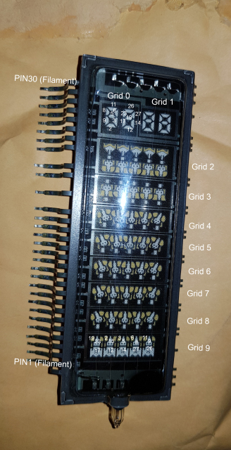
To check the VFD was in good working order I connected 3v across the filament (pins 1 and 30).
I then connected 12v to a grid and a VFD plate (0v connected to the filament)
For example, connecting 12v to pin 4 selects grid 9 (the bottom row), and 12v to pin 17 lights the bottom half of the first ship.
IF I moved 12v from pin 4 to pin 7 that would result in the bottom half of the first ship in the second row being lit instead.
I checked each part of my VFD and it works perfectly.
Note. The voltages used may not be correct, but it was good enough to test the VFD. Based on my research the filament voltage is likely to be about right, but I wouldn't run the VFD with those voltages permanently without checking they're correct.
Last edited by bobmoo79 on Sun Dec 23, 2018 6:47 am; edited 1 time in total |
|
| Back to top |
|
|
bobmoo79
Microvision
Joined: 07 Dec 2018
Last Visit: 14 Apr 2021
Posts: 25
Location: Southampton, UK
|
| Posted: Mon Dec 17, 2018 1:54 am Post subject: |
|
|
Ok so I have now drawn out most of the schematic but inevitably there are a couple of points that are currently preventing me from finishing.
1) First R05 is confusing. I can't seem to figure out what the resistor pack value is.
Edit: solved. The resistor pack contains 5 x 22k resistors. No common pin.
2) I don't yet fully unerstand the transformer.
This is what I know:
Pins 7 and 9 are not connected to anything on the PCB.
Pins 1, 2, and 5 are GND.
Pin 3 = +6v.
Pin 4 = Collector S02.
Pin 10 = VFD filmant (Pin30)
Pin 6 = VFD filament (pin 1)
Pin 8 = unknown.
Blanka, if you do have the schematic or if you can offer any help that would really be appreciated.
You also mentioned you were doing a video on this game. Does it include any technical details or is it purely a demonstration/review?
Last edited by bobmoo79 on Fri Dec 28, 2018 6:19 am; edited 2 times in total |
|
| Back to top |
|
|
bobmoo79
Microvision
Joined: 07 Dec 2018
Last Visit: 14 Apr 2021
Posts: 25
Location: Southampton, UK
|
| Posted: Thu Dec 27, 2018 6:37 am Post subject: |
|
|
A quick update now that all transistors have arrived and I have replaced them all.
A summary:
D882 still gets excessively hot.
The circuit is drawing 1.7A.
The UPD553 is only getting around -5vdc as a supply and appears to be doing nothing.
I have checked the VFD out of circuit and all sections work perfectly.
Rechecked all resistors again. All show the correct value. None are shorted or open.
Rechecked all caps. None are short circuit.
Rechecked all diodes again. All appear fine, except S06 which shows 20ohm in both directions but only appears to drive the speaker so I'm not bothered about this for now.
I have now run out of ideas completely and I can't make much sense of the schematic I created. My old electronics knowledge has well and truly left me. Wow I thought I'd remember more than I Do!
Last edited by bobmoo79 on Wed Jan 09, 2019 1:31 am; edited 2 times in total |
|
| Back to top |
|
|
blanka
Atari Cosmos
Joined: 14 Dec 2010
Last Visit: 13 Oct 2022
Posts: 561
Location: Eindhoven, the Netherlands
|
| Posted: Thu Dec 27, 2018 11:20 am Post subject: |
|
|
What the circuit does is apply 6V on/off very quickly to the transformer. Combined with the capacitor you get a dirty sine like signal, that allows transformation. This is the whole idea of switching power supplies: they allow DC-DC transforming quite easily.
_________________
Making the book on handheld games: www.2kboffun.com |
|
| Back to top |
|
|
bobmoo79
Microvision
Joined: 07 Dec 2018
Last Visit: 14 Apr 2021
Posts: 25
Location: Southampton, UK
|
| Posted: Fri Dec 28, 2018 5:57 am Post subject: |
|
|
| blanka wrote: | | What the circuit does is apply 6V on/off very quickly to the transformer. Combined with the capacitor you get a dirty sine like signal, that allows transformation. This is the whole idea of switching power supplies: they allow DC-DC transforming quite easily. |
Thanks Blanka, you talking about C04?
That goes from S02 emitter to base of S04.
Blanka Did you find a schematic for Astro Wars / Galaxy II that you could post here?
I completed mine as best I could but I think I need to check it again. Would be useful to have a known good drawing to work from.
I have now replaced all electrolytic caps because it was cheap to do so.
Still no joy.
I'm now considering removing the UPD553 and wiring up a simple test circuit on stripboard to see whether I can get some signs of life, possible just by wiring the speaker up so I can at least hear sound (hopefully).
Last edited by bobmoo79 on Wed Jan 09, 2019 1:09 am; edited 1 time in total |
|
| Back to top |
|
|
bobmoo79
Microvision
Joined: 07 Dec 2018
Last Visit: 14 Apr 2021
Posts: 25
Location: Southampton, UK
|
| Posted: Tue Jan 15, 2019 1:59 am Post subject: |
|
|
So I was lucky enough to come across a cheap non-working Astro Wars (red text - first edition), or at least that's how it was described. The seller said that when powered up the system made all the right noises and appeared to be functioning correctly but that the VFD was not coming on. Perfect for me as the broken unit I already owned had a working VFD.
But when I received my new purchase the first thing I did was put batteries in and it works perfectly!!
so now I have one good unit (red text) and one bad unit (white text)
The new one has a slightly different PCB revision but there are no major circuit changes.
I have managed to measure voltages at key points around the working unit and I hope this will help me trouble shoot my broken one.
I'll add measured voltages to this thread later in the hope it can help somebody else with a broken unit.
On the broken unit I discovered something by accident.
If S06 is removed from the circuit I get -10v at the supply of the UPD553, which is as it should be. If the S06 is in circuit the voltage drops right down.
I mentioned before that I was unable to figure out what S06 is supposed to be, but it looks like this:

(it is a glass case, with red band at one end, thinner gold band just in from that, no text printed on the case.)
It measures 20ohms in both directions when tested with a DVM. I still need to remove the good one from the red unit and test it.
Last edited by bobmoo79 on Wed Jan 16, 2019 2:43 am; edited 1 time in total |
|
| Back to top |
|
|
bobmoo79
Microvision
Joined: 07 Dec 2018
Last Visit: 14 Apr 2021
Posts: 25
Location: Southampton, UK
|
| Posted: Wed Jan 16, 2019 1:11 am Post subject: |
|
|
So last night I only had 10 minutes and I decided to take the plunge.
Because after removing S06 I measured the micro was receiving the full -10v that it is supposed to get, I wondered whether it was actually running. No sounds were made, BUT I'd expect that with the removal of S06 anyway. VFD was not getting the required voltage and so nothing displayed at this point.
Yes I could have found my scope and attached that to the circuit.
Or I could have removed the microcontroller and constructed a test circuit as previously suggested, but I only had 10 minutes and I'm impatient.
So I powered the main PCB with 6v as is usual but then used a second power supply to apply -6v to one of the VFD filament pins (Pin 30) and the result speaks for itself.
https://youtu.be/hWjfrqlpPds
LIFE!
So now I know for sure that the VFD, microcontroller, oscillator etc all work correctly. I'm still not getting the voltages I need from the power circuit, although I have already replaced all the transistors, confirmed the resistor values, tested some diodes, and confirmed no short circuits on any caps.
I still need to identify S06 and am confident this is definitely faulty. I still need to replace it with the equivalent from the working unit (which is actually slightly different in this part of the circuit) to see what the impact is.
But there aren't many components left to investigate so I'm confident I'll get there, even if I still don't understand the circuit. Yes, it's starting to look like trial and error 
Last edited by bobmoo79 on Mon Jan 21, 2019 1:23 am; edited 1 time in total |
|
| Back to top |
|
|
bobmoo79
Microvision
Joined: 07 Dec 2018
Last Visit: 14 Apr 2021
Posts: 25
Location: Southampton, UK
|
| Posted: Thu Jan 17, 2019 3:18 am Post subject: |
|
|
Removed the S06 from working Unit and soldered it onto the faulty unit and it works flawlessly (!)
so after all this time suspecting S06 is the problem I have finally proven it. Now to decide what S06 actually is.
I added it to my simple diode test circuit and cranked up the voltage in the hope that I'd identify the zener voltage. It didn't work but my power supply is limited to about 31.5v and I thought this could be a 32v zener diode. Not enough juice to confirm my suspicion  |
|
| Back to top |
|
|
bobmoo79
Microvision
Joined: 07 Dec 2018
Last Visit: 14 Apr 2021
Posts: 25
Location: Southampton, UK
|
| Posted: Sat Jan 19, 2019 3:32 am Post subject: |
|
|
| Measured the zener voltage as 39v while in circuit. Already ordered a 32v zener so will try that when it arrives later today |
|
| Back to top |
|
|
TokyoBatman
Gakken Dig Dug

Joined: 18 May 2018
Last Visit: 12 Aug 2020
Posts: 154
Location: Tokyo, Japan
|
| Posted: Sat Jan 19, 2019 6:46 am Post subject: |
|
|
Very nice! I've been following along with your updates. So if S06 is a 32v diode. Will this be a wrap on the project?
If you measued 39v while in circuit, what is this saying about the chances of the S06 being a 32v diode. Would you need to move up to a 39v zenner diode to match? |
|
| Back to top |
|
|
|